

In An Ac Capacitive Circuit
A capacitor is i of the virtually used electronic components. Information technology has the ability to store energy inside it, in the form of an electric accuse producing a static voltage (potential difference) across its plates. Only, a capacitor is similar to a small rechargeable bombardment. A capacitor is just a combination of ii conductive or metallic plates places parallel, and are electrically separated by expert insulating layer (also chosen Dielectric) made up of waxed paper, mica, ceramic, plastic and etc.
There are many applications of a capacitor in electronics, some of them are listed below:
- Energy Storage
- Ability Conditioning
- Ability factor Correction
- Filtration
- Oscillators
Now, the point is how a capacitor work? When you connect power supply to the capacitor it blocks the DC current due to insulating layer, and permit a voltage to be present beyond the plates in the class of electrical accuse. So, you know how a capacitor works and what are its uses or application, just you accept to learn that how to utilise a capacitor in electronic circuits.
How to Connect a Capacitor in Electronic Excursion?
Here, we are going to demonstrate you the connections of a capacitor and effect due to it with examples.
- Capacitor in Series
- Capacitor in Parallel
- Capacitor in Air conditioning Circuit
Capacitor in Serial Excursion
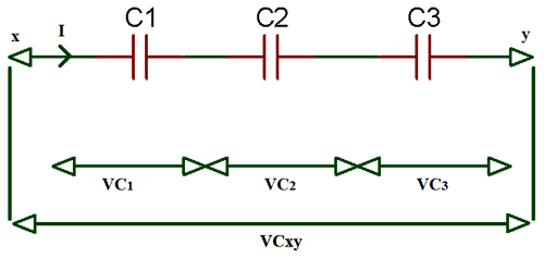
In a circuit, when you connect capacitors in serial as shown in the higher up prototype, the total capacitance is decreased. The electric current through capacitors in series is equal (i.e. iT = i1 = iii = i3= in). Hence, the charge stored by the capacitors is as well the same (i.e. QT = Qi = Q2 = Qiii), considering charge stored past a plate of any capacitor comes from the plate of next capacitor in the excursion.
By applying Kirchhoff'southward Voltage Law (KVL) in the circuit, we accept
VT = VC1 + VC2 + VC3 … equation (one)
As we know,
Q = CV So, V = Q / C
Where, FiveC1 = Q / C1; VC2 = Q / Ctwo; VC3 = Q / C3
At present, on putting the above values in the equation (1)
(1 / CT) = (ane / C1) + (i / C2) + (1 / C3)
For north number of capacitor in serial the equation will be
(1 / CT) = (1 / C1) + (ane / C2) + (1 / Ciii) + …. + (1 / Cn)
Hence, the higher up equation is the Serial Capacitors Equation.
Where, CT = Total capacitance of the excursion
C1…n = Capacitors capacitance
Capacitance Equation for two special cases is adamant below:
Case I: if there are two capacitor in series, with unlike value the capacitance will be expressed equally:
(1 / CT) = (C1 + C2) / (Cane * C2) Or, CT = (Cone * Ctwo) / (Cone + C2) … equation (2)
Case 2: if there are ii capacitor in serial, with same value the capacitance volition be expressed as:
(1 / CT) = 2C / C2 = 2 / C Or, CT = C / 2
Example for Series Capacitor Circuit:
Now, in the below example nosotros will prove you how to summate total capacitance and individual rms voltage drop across each capacitor.
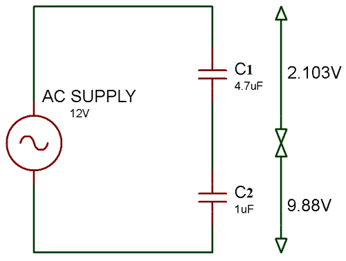
As, per the above circuit diagram at that place are two capacitors connected in series with dissimilar values. And so, the voltage drop beyond the capacitors is also diff. If we connect two capacitors with same value the voltage drib is too aforementioned.
Now, for the full value of capacitance we will utilize the formula from equation (2)
So, CT = (C1 * Ctwo) / (C1 + C2) Here, Cane = 4.7uf and C2 = 1uf CT = (4.7uf * 1uf) / (4.7uf + 1uf) CT = iv.7uf / 5.7uf CT = 0.824uf
At present, voltage drop across the capacitor C1 is:
VC1 = (CT / C1) * VT VCone = (0.824uf / four.7uf) * 12 VC1 = 2.103V
Now, voltage drop beyond the capacitor C2 is:
VC2 = (CT / C2) * VT VC2 = (0.824uf / 1uf) * 12 VC2 = nine.88V
Capacitor in Parallel Circuit
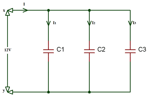
When you connect capacitors in parallel, then the total capacitance will exist equal to the sum of all the capacitors capacitance. Because the top plate of all the capacitors are connected together and the bottom plate also. So, by touching each other the constructive plate area is likewise increased. Therefore, the capacitance is proportional to the ratio of Area and distance.
By applying Kirchhoff's Current Law (KCL) in the to a higher place excursion,
iT = i1 +i2 + i3
As nosotros know current through a capacitor is expressed equally;
i = C (dV / dt ) So, iT = C1 (dV / dt ) + Cii (dV / dt ) + C3 (dV / dt ) And, i T = (C1 + C2 + Ciii)* (dV / dt ) iT = CT (dV / dt ) … equation (3)
From equation (3), the Parallel Capacitance equation is:
CT = C1 + C2 + C3
For northward number of capacitors connected in parallel the in a higher place equation is expressed equally:
CT = Cane + C2 + C3 + … + Cn
Example for Parallel Capacitor Circuit
In the below circuit diagram, in that location are iii capacitors continued in parallel. Equally these capacitors are continued in parallel the equivalent or total capacitance will be equal to the sum of the individual capacitance.
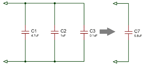
CT = C1 + C2 + C3 Where, Cane = 4.7uf; Cii = 1uf and Cthree = 0.1uf So, CT = (4.seven +ane + 0.1)uf CT = 5.8uf
Capacitor in Ac circuits
When a capacitor is continued to DC supply, then the capacitor starts charging slowly. And, when the charging current voltage of a capacitor is equal to the supply voltage it's said to fully charged condition. Hither, in this condition the capacitor works every bit an energy source equally long every bit voltage is applied. Also, capacitors do not let the electric current to pass through it after information technology get fully charged.
Whenever, Ac voltage is supplied to the capacitor as shown in to a higher place purely capacitive circuit. Then the capacitor charges and discharges continuously to every new voltage level (charges on positive voltage level and discharge on negative voltage level). The capacitor's capacitance in AC circuits depends on the frequency of input voltage supplied to the circuit. The current is directly proportional to the rate of change of voltage applied to the circuit.
i = dQ / dt = C (dV / dt )
Phasor diagram for Capacitor in AC Circuit
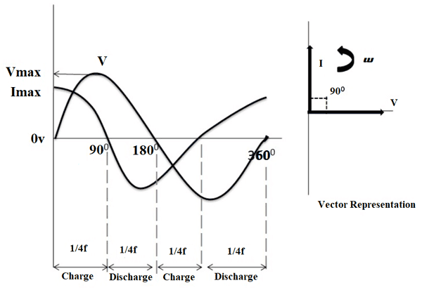
As yous see the phasor diagram for Air-conditioning capacitor in the below image, electric current and voltage are represent in sine wave. On observing, at 0⁰ the charging current is at its acme value because of the voltage increasing in positive management steadily.
Now, at xc⁰ there is no current menstruum through the capacitor considering the supply voltage reaches to the maximum value. At 180⁰ the voltage start decreasing slowly to zero and current attain to maximum value in negative direction. And, once more the charging reaches to its peak value at 360⁰, because of supply voltage is at its minimum value.
Therefore, from the above waveform we tin observe that the current is leading the voltage by xc⁰. And so, nosotros can say that the AC voltage lags the current by 90⁰ in an ideal capacitor circuit.
Capacitor Reactance (Xc) in Air conditioning Circuit
Consider the above circuit diagram, every bit we know Air conditioning input voltage is expressed as,
V = VgSinwt
And, capacitor charge Q = CV,
So, Q = CVmSinwt
And, current through a capacitor, i = dQ / dt
So,
i = d (CVmSinwt) / dt i = C * d (FivemSinwt) / dt i = C*5mCoswt *w i = w*C*VmSin(wt + π/2) at, wt = 0 sin(wt + π/2) = one hence, im = wCVm Vthousand / ig = 1 / wC
As we know, w = 2πf
So,
Capacitive Reactance (Xc) = Fivem / iyard = i / 2πfC
Case for Capacitive Reactance in Air-conditioning Excursion
diagram
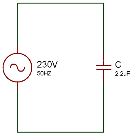
Allow'due south, consider the value of C = ii.2uf and the supply voltage V = 230V, 50Hz
Now, the Capacitive Reactance (Xc) = Vthou / im = 1 / 2πfC Here, C = 2.2uf, and f = 50Hz So, Xc = i / two*iii.1414*50*2.2*10-6 Xc = 1446.86 ohm

In An Ac Capacitive Circuit,
Source: https://circuitdigest.com/tutorial/capacitor-in-series-and-parallel-circuits
Posted by: bowennack1994.blogspot.com
0 Response to "In An Ac Capacitive Circuit"
Post a Comment